As electronics become more compact, powerful, and complex, Ball Grid Array (BGA) assembly has become an essential in modern PCB design. Their ability to support high pin counts and maintain signal integrity makes them ideal for advanced applications including aerospace, medical and industrial electronics.
However, with these benefits comes one critical challenge: ensuring long-term reliability. BGA assemblies can be susceptible to unique failure modes that demand careful attention during design, assembly, and inspection.
We explore some key factors that can influence the long-term performance of BGA assemblies, and consider how to mitigate these risks and avoid challenging BGA rework.
Understanding the Reliability Challenge
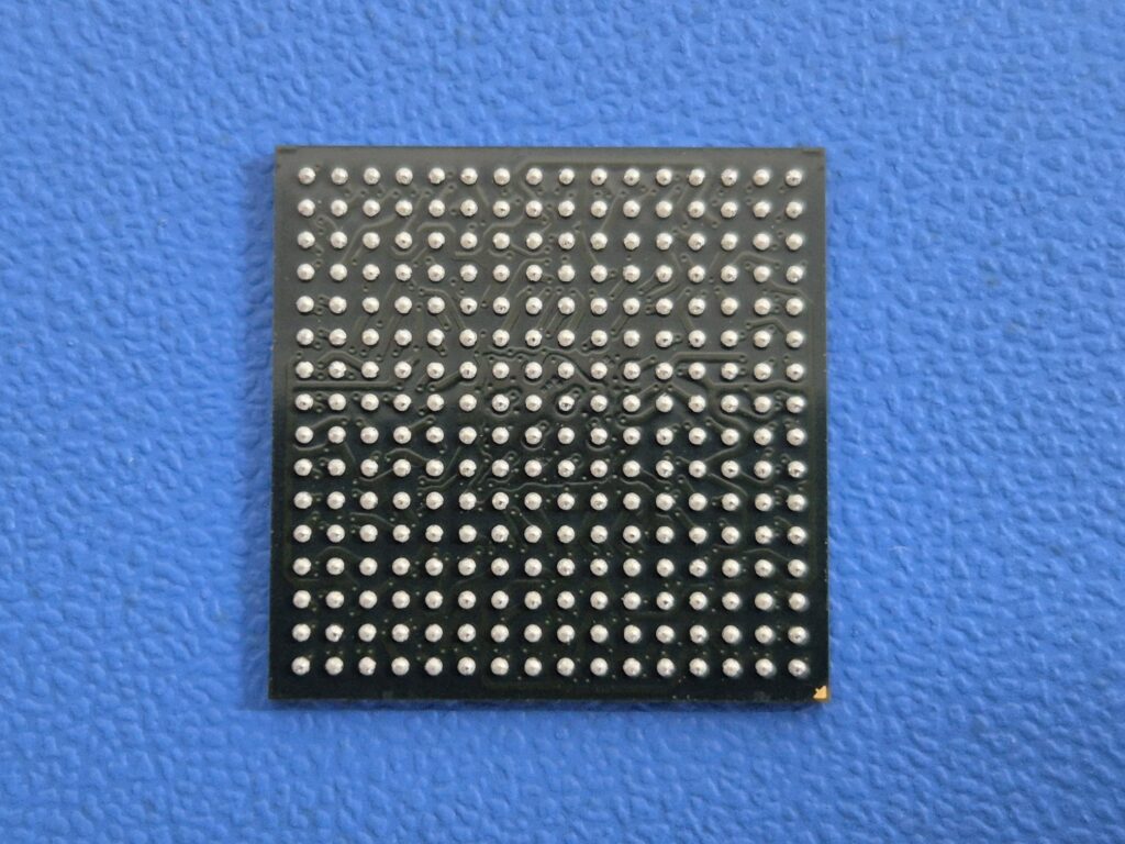
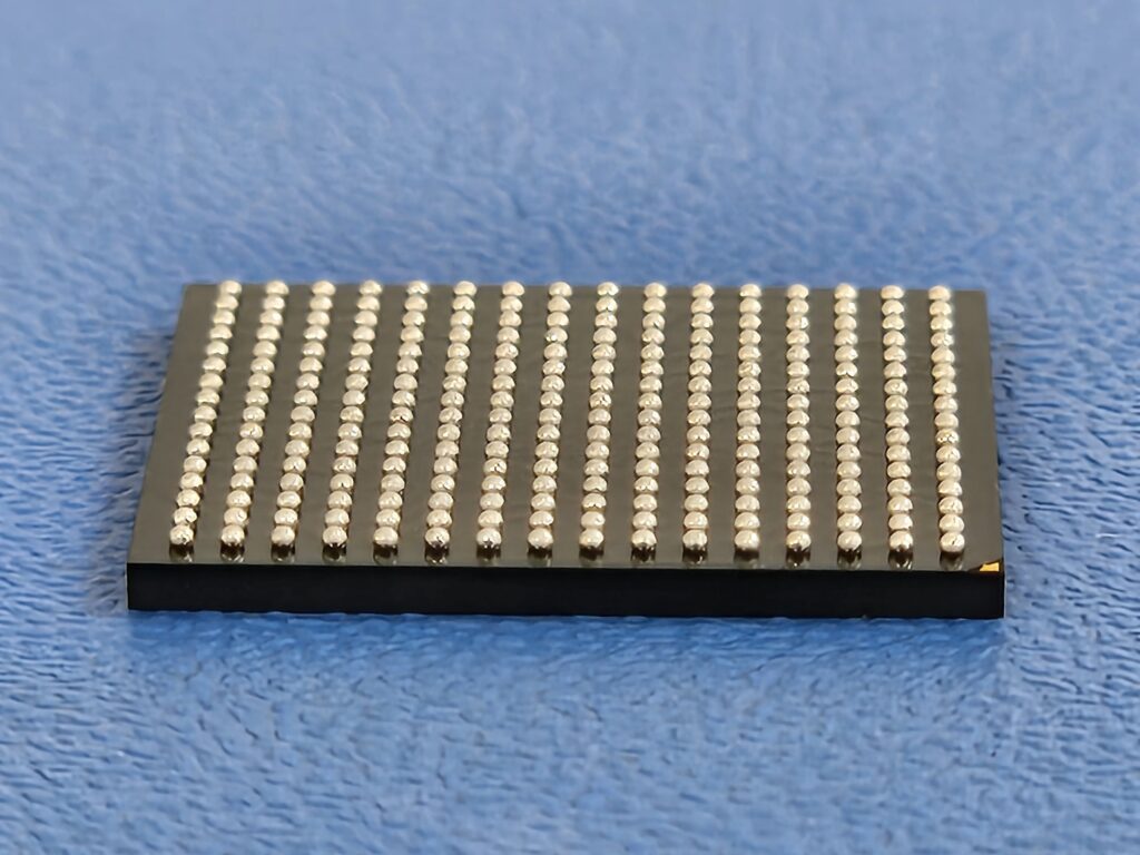
Unlike traditional leaded packages, including through-hole components and leaded surface-mount devices such as QFPs, BGA components connect to the PCB through an array of solder balls located beneath the package. These connections are not visible to the naked eye, which obviously makes manual defect detection impossible and therefore quality assurance more complex.
Additionally, thermal and mechanical stresses can degrade solder joints over time, leading to intermittent or catastrophic failures.
1. Design for Reliability (DfR)
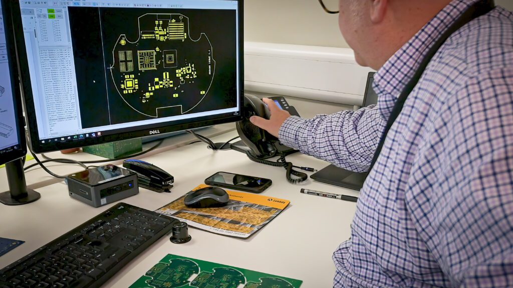
Reliability begins right at the very first design stage.
Engineers must account for:
- Thermal expansion: Differences in Coefficient of Thermal Expansion (CTE) between the PCB and the BGA package can cause solder joint fatigue over time.
- Pad and stencil design: Proper pad sizing and solder paste deposition are crucial for achieving uniform joints.
- PCB stack-up: Layer construction, material selection, and copper distribution all influence thermal performance and structural integrity.
Using simulation tools to model thermal cycles and mechanical stress can help to identify potential failure points before manufacturing begins.
2. High-Precision Assembly Techniques
The reliability of these PCBs hinges on flawless assembly execution.
Key steps of BGA assembly include:
- Accurate solder paste printing: Misalignment or inconsistent volume can lead to voids or bridging.
- Controlled placement: Pick-and-place machines must handle BGAs with extreme accuracy, considering the very small tolerance for positional error.
- Optimised reflow profiles: Thermal profiles should be tailored to ensure complete solder reflow without damaging the component or PCB.
Consistent, repeatable processes are essential. Manufacturers should follow IPC-A-610 Class II or III standards, depending on the criticality of the application.
3. Inspection and Quality Control
Because BGA joints are hidden, advanced inspection methods are required:
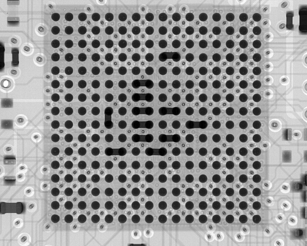
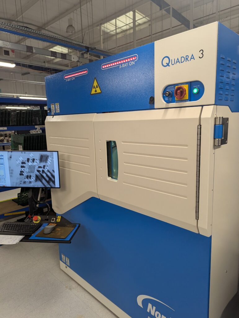
- X-ray inspection: X ray inspection is the primary method for detecting voids, cold joints, misalignment, and solder bridging. Using modern X-ray inspection machines like the Nordson Quadra 3, engineers can look through the entire PCB without any effect on the board.
- Automated Optical Inspection (AOI): While limited to visible features, AOI helps ensure component orientation and proper placement quickly.
- Electrical testing: In-circuit and functional testing verify that the assembly performs as expected under load conditions.
Regular process audits and statistical quality control further reduce defect rates and ensure consistency across batches.
4. Thermal and Mechanical Stress Testing
To predict long-term reliability, BGA assemblies should undergo:
- Thermal cycling: This simulates temperature changes to test solder joint fatigue.
- Vibration and shock testing: This is particularly important for automotive, aerospace, and defence electronics.
- Humidity and corrosion testing: This ensures the assembly performs under environmental exposure.
These tests are vital for identifying latent weaknesses that might only appear after months or years in service.
Rework and Repair Considerations For BGA Assemblies
BGA rework is possible; at Active-PCB Solutions we have the experience to undertake complex BGA repair work.
However, it must be done with care:
- Controlled reballing or reflow: Requires specialised equipment and expertise.
- Minimise cycles: Repeated heating can damage the PCB or nearby components.
- Use rework-specific profiles: Different from standard production to avoid thermal overstress.
Not all assemblies are candidates for rework and a cost-benefit analysis should guide the decision.
BGA assembly offers powerful advantages in high-density, high-performance electronics. But to fully realise those benefits, reliability must be engineered into every stage of the process, from design to production to testing.
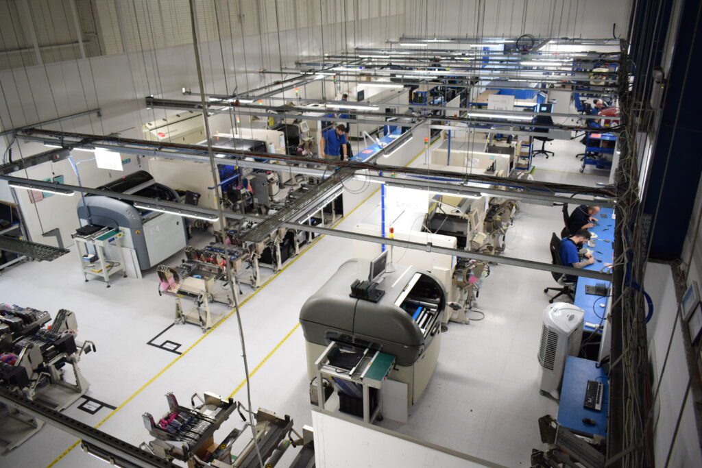
At Active-PCB Solutions, we specialise in high-reliability BGA assembly, supporting sectors where failure is not an option.
With a consistent investment in new equipment, IPC-certified processes, and a commitment to quality, we help ensure your assemblies deliver dependable performance for years to come.
Contact us today to learn how we can support your next high-reliability project.